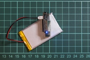
ESP12x LiPo Charge+ 3.3V Buck/Boost
Electronics
November 2017
Melbourne, Australia
The ESP12x LiPo Charge+ 3.3V Buck/Boost board, along with its companion programmer board, was designed to address a particular gap in the electronic prototyping community: if you wanted to make a wireless, battery-powered ESP-12x based electronic project, you often have to work with big, bulky frankenstein setups. This design was borne out of a need to have a cheap, tiny but still accessible and hackable electronic prototyping system for my PhD research. The ESP8266 family of boards are great for their price, but also consequently unfriendly for use (beyond breadboard-style prototyping):
- Commonly-available breakout boards for the ESP8266 - ESP12x series increase the footprint of the ESP12x form factor due to the use of 0.1" pitch headers
- These boards include a basic linear 3.3V regulator that works well for 5V power sources, but are not ideal for using a 3.7V LiPo battery – a buck/boost regulator is needed to maximise the battery life fully*
- With the exception of the Adafruit Feather Huzzah, there are no existing integrated solutions that combine a 3.7V single-cell lithium-polymer (LiPo) battery charger and buck/boost voltage regulator (considering the fact that a single-cell LiPo will go from 4.2V-2.8V through its charge cycle
- The Adafruit Feather Huzzah is a decent solution but it's flat, long footprint does not cater well to compact enclosures
- Putting together your own solution from third-party battery chargers and voltage regulator boards results in a footprint similar to the Adafruit Feather Huzzah
* Yes, this is a contentious claim. Conventional wisdom advises that LiPo batteries not be over-drained. By 'over-drained', this would mean discharging the battery to around 2.8V, the voltage where LiPos with built-in protection circuits will cutoff. The concept is that by using a low dropout linear 3.3V regulator, the LiPo battery will discharge from 4.2V down to about 3.4V, and always maintain quite a decent minimum charge. Using a buck/boost regulator, on the other hand, utilises battery capacity more fully, at the potential risk of over-drain. However, if using a LiPo battery from a reputable source that has the built-in protection circuitry, the only thing to be concerned about would be the possibly reduced lifespan of a battery that's allowed to discharge too much. More tests with this will reveal real-world answers.
What's new?
My design uses the compact MCP73831 lipo charger IC, and couples it with the TPS63060 buck/boost IC-based solution from Pololu. Everything is stacked and crammed into a tight arrangement. The board has the following features:
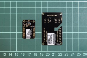
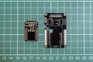
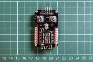
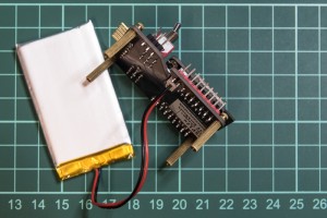
- Compact footprint – 20mm (w) x 29.85mm (l) (35.65mm including ESP12x antenna protrusion) x 11.5mm (h)
- Micro USB charging jack – plug it into any USB port to charge the connected LiPo battery
- Selectable charge rates: 100mA or 500mA
- Serial-TTL interface is not included on-board, to keep size down. The board can be programmed via the programmer board (or via OTA once configured with existing OTA code)
- The programmer board works with an FTDI 3.3v USB-TTL cable, and has a cutout groove to allow the battery to remain attached while programming/testing
Schematics and details will be posted on my Github repository, once more findings are confirmed.
ESP12x LiPo Charge+ BuckBoost board
ESP12x LiPo Charge+ BuckBoost board
ESP12x LiPo Charge+ BuckBoost Programmer board
ESP12x LiPo Charge+ BuckBoost board
ESP12x LiPo Charge+ BuckBoost board

